|
Currently most FFR Roadsters with the IRS option have their cages bolted or welded in by the kit builder after the original build (as a live axle car). However, since we were able to order the IRS as an option on our new kit, the factory welded in the IRS cage and omitted the mounts for the live axle links and springs. |
|
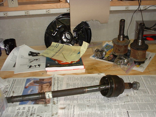
The T-bird halfshafts are too long for the narrower Cobra, so we had to remove the CV joints from the T-bird shafts and install them on shorter shafts that come with the IRS kit from FFR. This was a messy, thankless job. First we removed the larger joints (called the "plunge joints"). These came off relatively easily, even their inner pieces, which fit tightly to the shafts. You can see these parts at the upper right, to the right of the brake backing plates. |
|
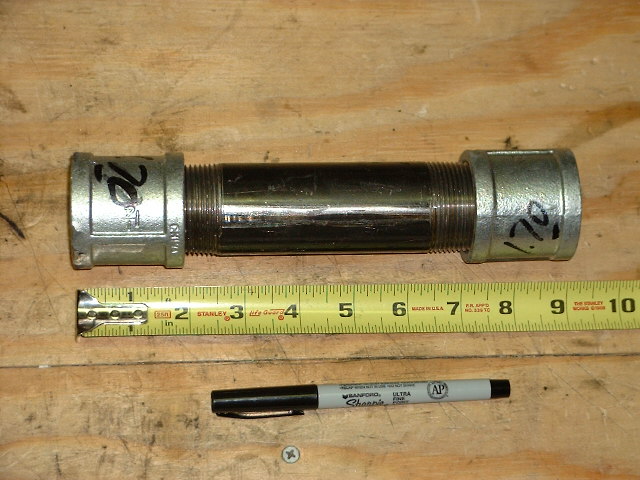
This prompted our first call to tech support. FFR engineer Jim Schenck said that they sometimes use a tube around the shaft to make this easier. Here you can see Nate using Hine-Pennington Racing special tool no. 00002, made up of plumbing parts from the local general store, to remove a CV joint. It worked great! |
|
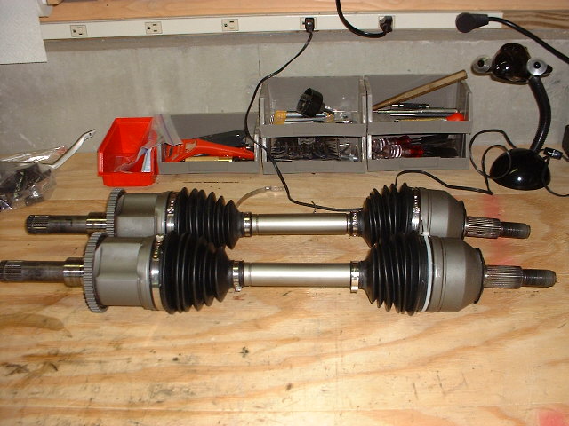
The ruler and pen are for size reference. |
|
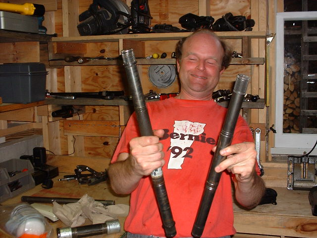
The T-bird shaft is on the left, and the new Cobra shaft is on the right. |
|
Inside the boots is a rather slimy mess, because the joints are filled with a grease to keep them from burning up under the massive power of the mighty Mustang 302. But we can't see that; only Nate had to look at it! Incidentally, for some reason one of the clamps for the boots was missing, and Nate misplaced another, but he was able to find generic replacements for them (intended for a front wheel drive car, of course!) at a local parts store. |
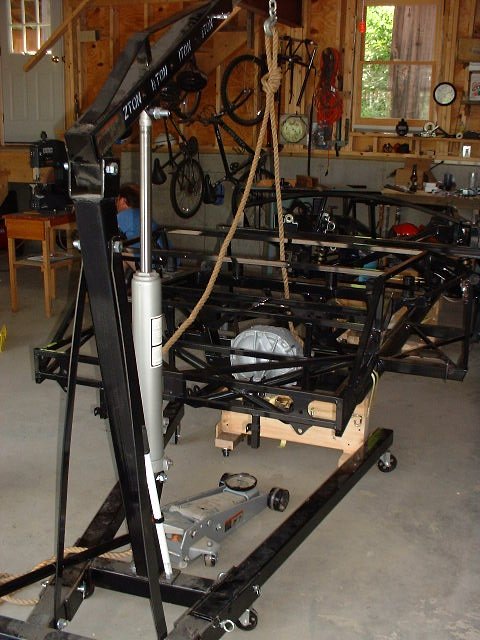
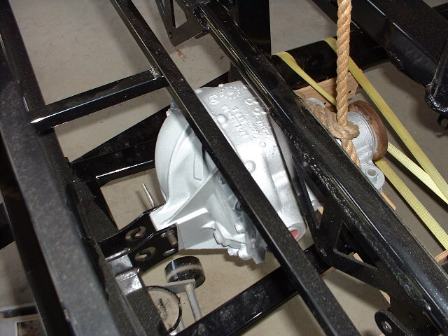
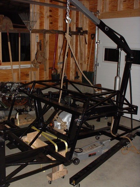 Well, now that we have halfshafts,
we need something to put them in. Here the differential gets
raised into the chassis, using the hoist above and floor jack
below. Well, now that we have halfshafts,
we need something to put them in. Here the differential gets
raised into the chassis, using the hoist above and floor jack
below. |
|
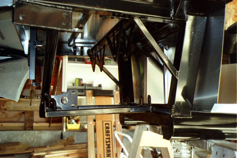
This was a tough job, because the differential barely fits through the IRS cage. It had to go up with its nose up, twist, go up some more, and then rotate into place. It didn't escape without getting a few scars on its fancy new paint job! |
 Finally the differential nestles
into its new home. I'll bolt it in later, after I've bought some
bolts that fit through the holes in the chassis. Finally the differential nestles
into its new home. I'll bolt it in later, after I've bought some
bolts that fit through the holes in the chassis. |
|
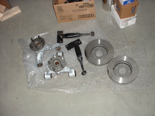
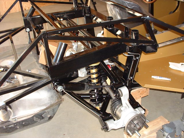
We went ahead and assembled as much as we could. At right are the springs, dampers, halfshafts, and assorted other components that will go into the rear suspension. |
|
At left are the aluminim spindles from the Thunderbird, looking almost new after we cleaned them up and Nate painted them with Eastwood Alumablast. At right are the new Thunderbird discs, and in the middle are the "quad shocks" from the Mustang. The quad shocks dampen rotational and longitudinal flexing of the rear suspension assembly under acceleration and braking, helping to prevent wheel hop. |
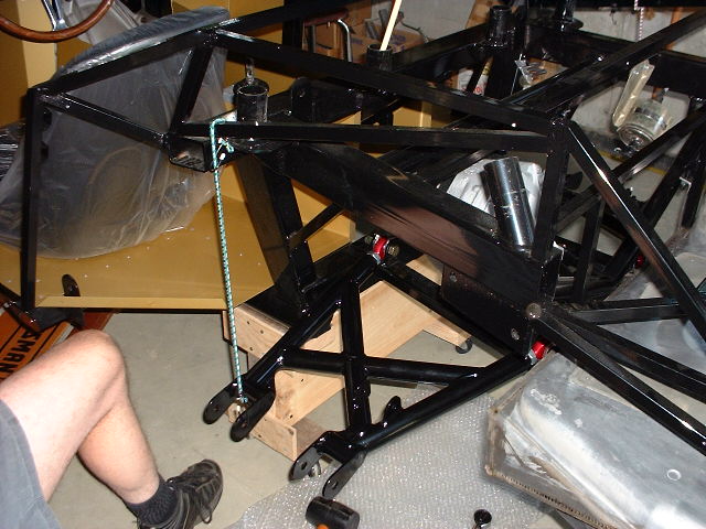
 Here Nate is tightening the
bolts holding the long-awaited left lower control arm in place. Here Nate is tightening the
bolts holding the long-awaited left lower control arm in place. |
|
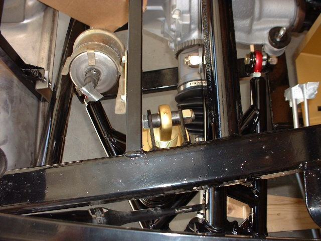
The bungee at left is holding up the control arm so it won't drop down too far and hit the frame at the inboard end, near the inboard rod ends. Oops! In this picture, the control arm is upside down and on the wrong side. The tabs for the spring/damper unit need to be on the bottom. Doh! There's a brief note to this effect in the IRS instructions, but in our eagerness to install the long-awaited parts, we overlooked that note. A call to FFR engineer Jim Schenck quickly resolved the problem. Of course, now Jim probably thinks we're totally out to lunch! |
|
Also note the quad shock, connected to the frame at the left and angling forward to its mounting tabs on the bottom of the upper control arm. The instructions said to mount the quad shocks with their bodies forward, but that produced tight clearances between them and the coil springs. After discussion with factory engineers, we decided to mount them with the bodies to the rear. If they don't clear the tires, we'll have to reverse them. |
|
The big can at left is the fuel filter. At right you can se the fuel lines (a main line and a smaller return line). These will soon be connected to the fuel filter and the fuel tank (at far left) by some increadibly expensive ($6 per foot!) high pressure flexible fuel lines. |
|
Nate has also mounted the inboard end of the brake line to the frame. Don't worry; the brake line isn't being stretched. Nate checked! Remember, right now the suspension is at full droop; when the car is sitting on its wheels, there will be considerable slack in the line. |
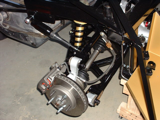
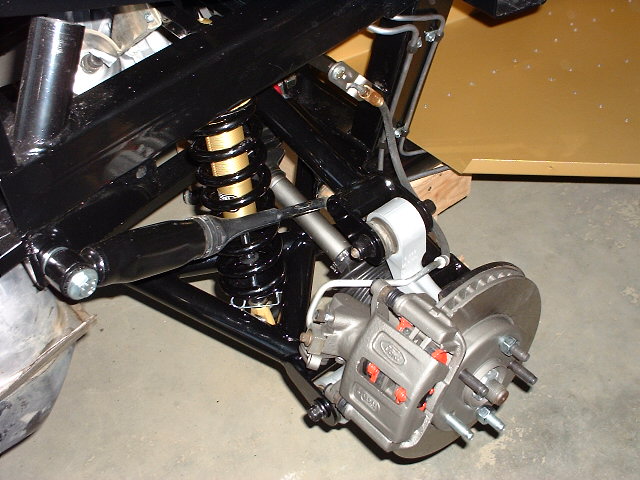 Here's another view of the
right rear suspension, this time from the rear quarter. Doesn't
it look cool? Here's another view of the
right rear suspension, this time from the rear quarter. Doesn't
it look cool? |
| As soon as that last upper link arrives, we'll finish installing the left side and it will become a mirror image of this. |